Thursday, May 11, 2017

2017 top 5 Best 3D Printers for Starters

Hello! Today I going to show you my lost of top 10 Most reliable 3D printers of the year 2017. This list is very personal. It comes from the experience of owning multiple printers and being in the 3D printers community as well as having friends who also own multiple 3D printers. As well as working with industrial 3D printers. All the printers that made it on the list are below $500 (sure there are some amount of tinkering that needs to go in there but one you dialed in, these are work horses)

Number 1 on this list.

Mp select Mini


For the cost of $200 this little dude is my number one recommended 3D printer for my fellow makers  who would like a cheap, reliable, quality bang for the buck 3 D printer. Recently Monoprice has released the V2 which sold out the first batch of 1000 printers in the first 2 weeks. Once again proves that this printer is worthy. But before I get into the V2. Let's talk about the classic.
Pros:

  • Fist most impressive thing is that it comes with a heated bed.
  • Solid metal frame
  • Hassle free, non DIY printer, comes in 1 piece and literally prints out of the box
  • Amazing print quality, best for $200 so far
  • Reliable, delivers every time once dialed in.
  • Huge community, I'm a part of it, very civic, nice helpful bunch of people.
  • A lot of room for mods and improvements. One of the most impressive mod is the bed expansion from 3DM. They are specialized in modifying the mini. You can really turn this machine into a professional printer.
  • I freaking love it.


Cons and possible improvements.

  • Well as much as I love it there are a few issues. They can be fixed though, with a little bit of tinkering but I guess this is also a pro? I don't know I feel like it is more of a con since it kinds of irritates me.
  • The  bed is a little bendy due to how "T.H.I.C" is it. Also I very much disagree with the routing of the bed wires. They are routed on the bottom which carves into the ziptie. I eventually re-routed the bed. While I was doing that I also went in and replaced the idlers, pulleys with metal ones since it plastics idlers was cutting into my timing belt which caused black bits to appear everywhere around the print area.
  • The second con is the design of the bowden tube where the filament is fed into the hot-end, it can be a hasle if your hot end ever gets clogged.
  • There is no cooling the control board. The board is Melzi so it can be faulty sometimes.
  • The control knob is very very annoying.
  • Very humble build volume 120x140x120


Well but you probably won't have to worry about any of that because the V2 is released. It is currently sold out right now. The improvements MP has made on the V2 includes: side cooling fan, Bed insulation and rewiring, metal extruder, better control knob, and it comes with a build-tak like build plate so there is no need for glass bed.
To sum up. Go buy this printer please you will not regret it.

Get it here for $200 aprox:
http://amzn.to/2rgau04

My second favorite on the list is the big boy Creality CR-10.


 Even though it is a kit, it comes mostly assembled and ready to go. It will probably take you half an hour to set up and you will be printing. Compare to the other DIY kits which can take up to 7 hours to set it up. (Cough.. Anet.. cough): if you  really don't have a problem with setting it up in 7 hours then Anet is not a bad choice. I heard people are having a problem with Anet power's supply sparking. I simply cannot risk something like that since I'm going to hit print and leave the house. Anyway back to CR 10.
Pros:

  • Fist thing you will notice right away is the build volume. The CR-10 is a giant, has a staggering 300 x 300 x 500 mm build volume.
  • Second is print quality. Despite the fact that this printer still provides very decent print quality. That isn't usually the case with large printers. 

Cons:

  • A lot of the cons is going to GearBest. They are known for being the worst retailer. They sometime send you returned machines and their customer service is amogst the worst of the worst. Please be advice. However, they list this printer on their website for as low as $409. Killer deal. 
  • Bed that comes with this printer is known for being bad. People seem to have a better time printing with the mirror glass. You can find it at your local home improvement stores.
Get this printer here on GearBest for $409.
The third printer is another Monoprice,

MP Select Maker V2

The third printer on this list is another re-brand from Monoprice. MP in my opinion has been and will be very skillful in term of picking the best printers from foreign country (China to be specific) and retail them. This printer is re-branded from the Wanhao Duplicator I3. Which costs way less than the Wanhao itself if you buy it from the U.S. This printer
Pros:
Even there will be some cheap upgrades and tweaks here and there. But once you dialed in, this printer is another work horse.
  • The Maker Select V2 comes in a kit, but the assembly process is very easy compares to the Prusa i3 clone kits.
  • Speaks G-code so has great compatibility with all the g-code slicer like Cura, Simplify 3D, and Repetier
  • Full-metal body frames mean that this printer can handle a helluva beating. 
  • This printer can produce high quality prints (100 microns maximum resolution)
  • There are a lot of room for mods. 
Cons
  • Needs a little tweaks before you can fully dial in
  • moderate bed-size, not too large not too small.
Get the Maker Select here for $319:


Monday, May 1, 2017

Project 1: Beta Release

Here are  a summary of what I have learned from this project.
RF: this first area is the most important because it have me a job in the field of RF engineering. Who iuld have thought. I never really paid attention in my EM classes but here I am. I've leaned transmition and reception. I've learned basic operations of antennas as well as transmitting and receiving signals through an wifi module. Nrf24L01 which is a great module. I would recommend using this module on your RC DIY, it has great range and can be further improved with modification, up to 100 meters straight line.

3D printing: this is second on the list because this is what I have been doing for the past 3 months now. Ever since I bought a 3D printer I was just hooked into how much you can do with your imagination. I have orinted hundreds of designs and I love every moment of it.  Trust me its fun as hell. If you are a creative/ DIY person who wants to make their own stuff please, get a 3D printer now if you dont already have one.

The third set of skills that I have gain has to do with what I went to school for. Electrical engineering related. I further improve these skillser by doing this prject. The first is Arduino designs, I'm now very comfortable with arduino related and I know many tricks to debug and havk arduino codes and circuits. My soldering skills amd PCB designing, laying out, and troubleshooting pcb also improved. On my recent design the for the receiver pcb the pins are not right, pin 10 and 11 were supposed to be 11 and 12. Which caused the nrf24l01 to not be working properly and I was not receiving any signal. It was a hassle to debug. I also learned regulators circuits inlcuding buck converts and standards regulating designing using transistors. Though the design was not perfect I was still getting pretty close operating voltages for my headligjts and servos. One problem with the PCB though one of the switches are not working properly om the transmittor board which for some reason I can not seem to find the .brd schematic. I might have deleted it accidentally which totally blows. Luckily I have 2 switches there so I emded up just using the other switch instead. One of the switches was supposed to be operation mode. Flipping that switch is supposed to send a bunch of operating sequences that control how my RC behaves. Oh well I dont really need it anyway so it is okay to leave it out for now I guess.

The final import set of skills that I've leaned is 3D modeling. I use schetchup becaise it is free amd it gets the job done. It is not the best 3D designing tool if you are really making money you can go with the industrial softwares. Anyhow st my current state I'm efficient enough to make any designs that you want as long as you give me the dimensions of the part. I already make some money 3D printing and I predict that it is only going to get better.

For my Next project I'm designing 3D printed Riven blade from Leage of legends with LEDs integrated. Stay tuned I think thisnis going to be fun and beneficial.

As the conclusion here is the robot. Please feel free to check him out at my YouTube channel
.


Monday, April 24, 2017

New and Improved Front Sterering System

So I thought my RC Robot was a little low. I bought 4 new monster wheels which bas 130mm in diameter and boy does it look good on my RC. Only 1 problem though, the front sterring arms was carving into the side of my wheels. Also the wheels are locked when they turn due to the fact that my previously designed axle are very short. So it is time for a new upgrade.
My new design consist of a longer axle and a better steering system which has a longer steering arms. The steering links are connected to both wheels to ensure even power distribution. The previous design only has one steering arm attached to the right front wheel. This works on a smaller wheel, however on a more massive wheel there seems to be a power issue. The front left wheel was very unresponsive.
I highly recommend the new design if you are interested in printing this. You can find the stls at my Thingiverse page:
http://www.thingiverse.com/thing:2245652
http://www.thingiverse.com/thing:2170283


Tuesday, April 11, 2017

3D Printer neopixel enclosure

PROJECT 2: 3D PRINTER ENCLOSURE


So I decided to make an enclosure for my 3d printer (mp select mini). After researching for a while the most affordable and possibly the easiest way to build an enclosure for my mini is the Lack table from Ikea method. There is a tutorial on how to make one on instructables.com but i did not go that route but instead. I designed my own enclosure. Now the number one problem that i have with this printer is noise. I live in a very small space so I'd like to get some sleep and still be able to print/design. The most popular reason why people want to go with this enclosure is heat. An enclosure is very ideal for printing ABS .
My enclosur consists of 2 Ikea Lack tables stack on top of each others. I glued the legs to the top of the bottom table and drill a hole to insert a pin between the legs. You can easily print out your own pins. For me I was using the pins I bought from Lowes.

The next step is to enclose four sides somehow. Thats when I bought 1 piece of 18x24 arcrylic sheet and cut it to size for my front door. On the sides I bought 3 pieces of congugated plastic because they ar super cheap and they get the job done. Then I cut them to size and glued them on the sides of the top table.

The next step is attaching noise insulation foams. These foams ar designed to absorb some of the soud energy therefore reduce the noise level. Probably not by much but good enough for me.

After that I drilled a hole in th back to feed the power cable through and voila. You have your enclosure. It looks pretty neat. It does make me feel like it's a chamber. Maybe I'll call it the mini chamber.


For the glass door you can print out a latch and attach it to the sides. Itl work pretty well too. You can stop here but since I have a couple of electronic sitting around. I decided to pimp it. :))
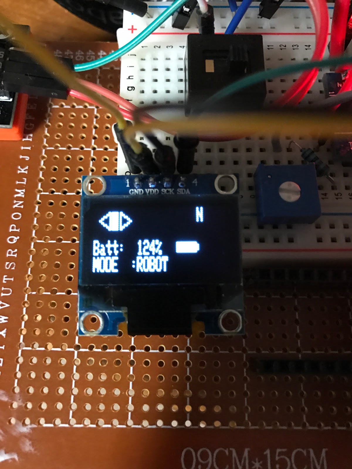
Heres what it looks like with the electronics


The Control box consists of 1 Arduino Uno (Micro controller), 1 TFT Touchscreen Display, 1 Battery pack (9.6V RC) battery, this one is Lithium Nickel I think. And a LM298 Motor Driver. All of these components are spare since I've upgraded my RC project I no longer need these. And I did not want to throw it away either. I mainly use the motor driver for that 5V regulator. There are 2 voltage sources on the side leaving room for improvement in the future. You do not have to use it. Yo u can just use a 5V regulator and it should be good. The Neopixel and the Arduino combine I think draw less than half of an Amp. So your IC chip should be enough to supply for these.
The  LOADS:
There are 2 loads. 1 is the Neopixel Ring from Adafruit. which is super colorful and super fun to play with. Costs only about $10.

The other load is the temperture sensor from ebay. This guy is also very affordable. The name is DHT11 Sensor. There is a library for it for Arduino so it was super easy to work with. And the temperature reading is quite accurate.


Connecting/Wiring is pretty straigh forward, For Neopixel, connect the data in pin to Arduino pin number 5 (written in the code), and temperature sensor pin to pin number 10. Vcc to Vcc and GND to GND. If you are not sure what this mean please contact me.


Okay.
So here is the code for the arduino
://neopixel package sections
#include <Adafruit_NeoPixel.h>
#ifdef __AVR__
  #include <avr/power.h>
#endif

#define PIN 5

#define NUM_LEDS 60

#define BRIGHTNESS 50

Adafruit_NeoPixel strip = Adafruit_NeoPixel(NUM_LEDS, PIN, NEO_GRBW + NEO_KHZ800);

int gamma[] = {
    0,  0,  0,  0,  0,  0,  0,  0,  0,  0,  0,  0,  0,  0,  0,  0,
    0,  0,  0,  0,  0,  0,  0,  0,  0,  0,  0,  0,  1,  1,  1,  1,
    1,  1,  1,  1,  1,  1,  1,  1,  1,  2,  2,  2,  2,  2,  2,  2,
    2,  3,  3,  3,  3,  3,  3,  3,  4,  4,  4,  4,  4,  5,  5,  5,
    5,  6,  6,  6,  6,  7,  7,  7,  7,  8,  8,  8,  9,  9,  9, 10,
   10, 10, 11, 11, 11, 12, 12, 13, 13, 13, 14, 14, 15, 15, 16, 16,
   17, 17, 18, 18, 19, 19, 20, 20, 21, 21, 22, 22, 23, 24, 24, 25,
   25, 26, 27, 27, 28, 29, 29, 30, 31, 32, 32, 33, 34, 35, 35, 36,
   37, 38, 39, 39, 40, 41, 42, 43, 44, 45, 46, 47, 48, 49, 50, 50,
   51, 52, 54, 55, 56, 57, 58, 59, 60, 61, 62, 63, 64, 66, 67, 68,
   69, 70, 72, 73, 74, 75, 77, 78, 79, 81, 82, 83, 85, 86, 87, 89,
   90, 92, 93, 95, 96, 98, 99,101,102,104,105,107,109,110,112,114,
  115,117,119,120,122,124,126,127,129,131,133,135,137,138,140,142,
  144,146,148,150,152,154,156,158,160,162,164,167,169,171,173,175,
  177,180,182,184,186,189,191,193,196,198,200,203,205,208,210,213,
  215,218,220,223,225,228,231,233,236,239,241,244,247,249,252,255 };
//END neopixel includes

//***********************************TOUCH SCREEN PACKAGE SECTIONS
#include <dht.h>
dht DHT;
// Paint example specifically for the TFTLCD breakout board.
// If using the Arduino shield, use the tftpaint_shield.pde sketch instead!
// DOES NOT CURRENTLY WORK ON ARDUINO LEONARDO

// Modified for SPFD5408 Library by Joao Lopes
// Version 0.9.2 - Rotation for Mega

// *** SPFD5408 change -- Begin
#include <SPFD5408_Adafruit_GFX.h>    // Core graphics library
#include <SPFD5408_Adafruit_TFTLCD.h> // Hardware-specific library
#include <SPFD5408_TouchScreen.h>
// *** SPFD5408 change -- End


#if defined(__SAM3X8E__)
    #undef __FlashStringHelper::F(string_literal)
    #define F(string_literal) string_literal
#endif

// When using the BREAKOUT BOARD only, use these 8 data lines to the LCD:
// For the Arduino Uno, Duemilanove, Diecimila, etc.:
//   D0 connects to digital pin 8  (Notice these are
//   D1 connects to digital pin 9   NOT in order!)
//   D2 connects to digital pin 2
//   D3 connects to digital pin 3
//   D4 connects to digital pin 4
//   D5 connects to digital pin 5
//   D6 connects to digital pin 6
//   D7 connects to digital pin 7

// For the Arduino Mega, use digital pins 22 through 29
// (on the 2-row header at the end of the board).
//   D0 connects to digital pin 22
//   D1 connects to digital pin 23
//   D2 connects to digital pin 24
//   D3 connects to digital pin 25
//   D4 connects to digital pin 26
//   D5 connects to digital pin 27
//   D6 connects to digital pin 28
//   D7 connects to digital pin 29

// For the Arduino Due, use digital pins 33 through 40
// (on the 2-row header at the end of the board).
//   D0 connects to digital pin 33
//   D1 connects to digital pin 34
//   D2 connects to digital pin 35
//   D3 connects to digital pin 36
//   D4 connects to digital pin 37
//   D5 connects to digital pin 38
//   D6 connects to digital pin 39
//   D7 connects to digital pin 40

#define YP A3  // must be an analog pin, use "An" notation!
#define XM A2  // must be an analog pin, use "An" notation!
#define YM 9   // can be a digital pin
#define XP 8   // can be a digital pin

// Original values
//#define TS_MINX 150
//#define TS_MINY 120
//#define TS_MAXX 920
//#define TS_MAXY 940

// Calibrate values
#define TS_MINX 125
#define TS_MINY 85
#define TS_MAXX 965
#define TS_MAXY 905

// For better pressure precision, we need to know the resistance
// between X+ and X- Use any multimeter to read it
// For the one we're using, its 300 ohms across the X plate
TouchScreen ts = TouchScreen(XP, YP, XM, YM, 300);

#define LCD_CS A3
#define LCD_CD A2
#define LCD_WR A1
#define LCD_RD A0
// optional
#define LCD_RESET A4

// Assign human-readable names to some common 16-bit color values:
#define  BLACK   0x0000
#define BLUE    0x001F
#define RED     0xF800
#define GREEN   0x07E0
#define CYAN    0x07FF
#define MAGENTA 0xF81F
#define YELLOW  0xFFE0
#define WHITE   0xFFFF


Adafruit_TFTLCD tft(LCD_CS, LCD_CD, LCD_WR, LCD_RD, LCD_RESET);

#define BOXSIZE 120
#define PENRADIUS 3

#define MINPRESSURE 10
#define MAXPRESSURE 1000
int oldcolor, currentcolor;

TSPoint p;

void setup(void) {


  tft.reset();

  // *** SPFD5408 change -- Begin
//  uint16_t identifier = tft.readID();
//
//  if(identifier == 0x9325) {
//    Serial.println(F("Found ILI9325 LCD driver"));
//  } else if(identifier == 0x9328) {
//    Serial.println(F("Found ILI9328 LCD driver"));
//  } else if(identifier == 0x7575) {
//    Serial.println(F("Found HX8347G LCD driver"));
//  } else if(identifier == 0x9341) {
//    Serial.println(F("Found ILI9341 LCD driver"));
//  } else if(identifier == 0x8357) {
//    Serial.println(F("Found HX8357D LCD driver"));
//  } else {
//    Serial.print(F("Unknown LCD driver chip: "));
//    Serial.println(identifier, HEX);
//    Serial.println(F("If using the Adafruit 2.8\" TFT Arduino shield, the line:"));
//    Serial.println(F("  #define USE_ADAFRUIT_SHIELD_PINOUT"));
//    Serial.println(F("should appear in the library header (Adafruit_TFT.h)."));
//    Serial.println(F("If using the breakout board, it should NOT be #defined!"));
//    Serial.println(F("Also if using the breakout, double-check that all wiring"));
//    Serial.println(F("matches the tutorial."));
//    return;
//  }
//
//  tft.begin(identifier);

  tft.begin(0x9341); // SDFP5408

  tft.setRotation(0); // Need for the Mega, please changed for your choice or rotation initial

  // Border

  drawBorder();

  // Initial screen

  tft.setCursor (55, 50);
  tft.setTextSize (6);
  tft.setTextColor(BLUE);
  tft.println("ECU");

  tft.setCursor(40,100);
  tft.setTextSize(1);
  tft.println("Enviromental Control Unit");

  tft.setCursor(60,150);
  tft.setTextSize(1);
  tft.setTextColor(RED);
  tft.println("Khoa Au");
  tft.setCursor(60,160);
  tft.println("au0516.blogspot.com");

  tft.setCursor (70, 250);
  tft.setTextSize (1);
  tft.setTextColor(BLACK);
  tft.println("Tap to continue");

  // Wait touch
  waitOneTouch();

// *** SPFD5408 change -- End

  // -- End

  // Paint
  //--------------
  tft.fillScreen(BLACK);
  tft.drawRect(0, 0, BOXSIZE, BOXSIZE, RED);
  tft.drawRect(BOXSIZE, 0, BOXSIZE, BOXSIZE, RED);
  tft.setCursor (20, 20);
  tft.setTextSize (1);
  tft.setTextColor(RED);
  tft.println("Temperature");

  tft.setCursor (150, 20);
  tft.setTextSize (1);
  tft.setTextColor(RED);
  tft.println("Humidity");

  tft.setCursor (10, 180);
  tft.setTextSize (2);
  tft.setTextColor(WHITE);
  tft.println("NEOPIXEL CONTROL");
//
  tft.drawRect(10, 200, 40, 40, RED);
  tft.setCursor (20, 220);
  tft.setTextSize(1);
  tft.println("ON");
  tft.drawRect(50,200, 40, 40, RED);
  tft.setCursor (60, 220);
  tft.setTextSize(1);
  tft.println("OFF");

//
  pinMode(13, OUTPUT);
 //******************************Neopixel Sections
   Serial.begin(115200);
  // This is for Trinket 5V 16MHz, you can remove these three lines if you are not using a Trinket
  #if defined (__AVR_ATtiny85__)
    if (F_CPU == 16000000) clock_prescale_set(clock_div_1);
  #endif
  // End of trinket special code
  strip.setBrightness(BRIGHTNESS);
  strip.begin();
  strip.show(); // Initialize all pixels to 'off'

  //end neopixel section


}


void loop()
{


  digitalWrite(13, HIGH);
  ts.getPoint();
  digitalWrite(13, LOW);

  // if sharing pins, you'll need to fix the directions of the touchscreen pins
  //pinMode(XP, OUTPUT);
  pinMode(XM, OUTPUT);
  pinMode(YP, OUTPUT);
  //pinMode(YM, OUTPUT);

  // we have some minimum pressure we consider 'valid'
  // pressure of 0 means no pressing!

  if (p.z > MINPRESSURE && p.z < MAXPRESSURE) {
    /*
    Serial.print("X = "); Serial.print(p.x);
    Serial.print("\tY = "); Serial.print(p.y);
    Serial.print("\tPressure = "); Serial.println(p.z);
    */
 
    if (p.y < (TS_MINY-5)) {
      Serial.println("erase");
      // press the bottom of the screen to erase
      tft.fillRect(0, BOXSIZE, tft.width(), tft.height()-BOXSIZE, BLACK);
    }
    // scale from 0->1023 to tft.width

    // *** SPFD5408 change -- Begin
    // Bug in in original code
    //p.x = map(p.y, TS_MINY, TS_MAXY, 0, tft.height());
    p.x = map(p.x, TS_MINX, TS_MAXX, 0, tft.width());
    // *** SPFD5408 change -- End
    p.y = map(p.y, TS_MINY, TS_MAXY, 0, tft.height());
  }

 tft.fillRect(20,60,50,30,BLACK);
 tft.fillRect(150,60,50,30,BLACK);

//temperature sensor section
  DHT.read11(10);
  tft.setCursor (20, 60);
  tft.setTextSize (2);
  tft.setTextColor(BLUE);
  tft.print(DHT.temperature,1);

  tft.println(" C");

  tft.setCursor (150, 60);
  tft.setTextSize (2);
  tft.setTextColor(BLUE);
  tft.println((int)DHT.humidity,1);

  colorWipe(strip.Color(255, 0, 0), 2); // Red
  colorWipe(strip.Color(0, 255, 0), 2); // Green
  colorWipe(strip.Color(0, 0, 255), 2); // Blue
  colorWipe(strip.Color(0, 0, 0, 255), 2); // White

  // whiteOverRainbow(20,75,5);
 // pulseWhite(5);
 // rainbowFade2White(3,1,1);


////Neopixel section
//  colorWipe(strip.Color(255, 0, 0), 2); // Red
//  colorWipe(strip.Color(0, 255, 0), 2); // Green
//  colorWipe(strip.Color(0, 0, 255), 2); // Blue
//  colorWipe(strip.Color(0, 0, 0, 255), 2); // White
//
//  //whiteOverRainbow(20,75,5);
//
//  //pulseWhite(5);
//
//  // fullWhite();
//  // delay(2000);
//
//  //rainbowFade2White(3,3,1);
////End neopixel section

}

// Wait one touch

TSPoint waitOneTouch() {

  // wait 1 touch to exit function

  TSPoint p;

  do {
    p= ts.getPoint();

    pinMode(XM, OUTPUT); //Pins configures again for TFT control
    pinMode(YP, OUTPUT);

  } while((p.z < MINPRESSURE )|| (p.z > MAXPRESSURE));

  return p;
}

//****************************************************************NEOPIXEL METHODS*************************************
void drawBorder () {

  // Draw a border

  uint16_t width = tft.width() - 1;
  uint16_t height = tft.height() - 1;
  uint8_t border = 10;

  tft.fillScreen(BLACK);
  tft.fillRect(border, border, (width - border * 2), (height - border * 2), WHITE);

}
  void colorWipe(uint32_t c, uint8_t wait) {
  for(uint16_t i=0; i<strip.numPixels(); i++) {
    strip.setPixelColor(i, c);
    strip.show();
    delay(wait);
  }
}

void pulseWhite(uint8_t wait) {
  for(int j = 0; j < 256 ; j++){
      for(uint16_t i=0; i<strip.numPixels(); i++) {
          strip.setPixelColor(i, strip.Color(0,0,0, gamma[j] ) );
        }
        delay(wait);
        strip.show();
      }

  for(int j = 255; j >= 0 ; j--){
      for(uint16_t i=0; i<strip.numPixels(); i++) {
          strip.setPixelColor(i, strip.Color(0,0,0, gamma[j] ) );
        }
        delay(wait);
        strip.show();
      }
}


void rainbowFade2White(uint8_t wait, int rainbowLoops, int whiteLoops) {
  float fadeMax = 100.0;
  int fadeVal = 0;
  uint32_t wheelVal;
  int redVal, greenVal, blueVal;

  for(int k = 0 ; k < rainbowLoops ; k ++){
 
    for(int j=0; j<256; j++) { // 5 cycles of all colors on wheel

      for(int i=0; i< strip.numPixels(); i++) {

        wheelVal = Wheel(((i * 256 / strip.numPixels()) + j) & 255);

        redVal = red(wheelVal) * float(fadeVal/fadeMax);
        greenVal = green(wheelVal) * float(fadeVal/fadeMax);
        blueVal = blue(wheelVal) * float(fadeVal/fadeMax);

        strip.setPixelColor( i, strip.Color( redVal, greenVal, blueVal ) );

      }

      //First loop, fade in!
      if(k == 0 && fadeVal < fadeMax-1) {
          fadeVal++;
      }

      //Last loop, fade out!
      else if(k == rainbowLoops - 1 && j > 255 - fadeMax ){
          fadeVal--;
      }

        strip.show();
        delay(wait);
    }

  }


  //delay(500);


  for(int k = 0 ; k < whiteLoops ; k ++){

    for(int j = 0; j < 256 ; j++){

        for(uint16_t i=0; i < strip.numPixels(); i++) {
            strip.setPixelColor(i, strip.Color(0,0,0, gamma[j] ) );
          }
          strip.show();
        }

       // delay(2000);
    for(int j = 255; j >= 0 ; j--){

        for(uint16_t i=0; i < strip.numPixels(); i++) {
            strip.setPixelColor(i, strip.Color(0,0,0, gamma[j] ) );
          }
          strip.show();
        }
  }

  //delay(500);


}

void whiteOverRainbow(uint8_t wait, uint8_t whiteSpeed, uint8_t whiteLength ) {

  if(whiteLength >= strip.numPixels()) whiteLength = strip.numPixels() - 1;

  int head = whiteLength - 1;
  int tail = 0;

  int loops = 3;
  int loopNum = 0;

  static unsigned long lastTime = 0;


  while(true){
    for(int j=0; j<256; j++) {
      for(uint16_t i=0; i<strip.numPixels(); i++) {
        if((i >= tail && i <= head) || (tail > head && i >= tail) || (tail > head && i <= head) ){
          strip.setPixelColor(i, strip.Color(0,0,0, 255 ) );
        }
        else{
          strip.setPixelColor(i, Wheel(((i * 256 / strip.numPixels()) + j) & 255));
        }
     
      }

      if(millis() - lastTime > whiteSpeed) {
        head++;
        tail++;
        if(head == strip.numPixels()){
          loopNum++;
        }
        lastTime = millis();
      }

      if(loopNum == loops) return;
 
      head%=strip.numPixels();
      tail%=strip.numPixels();
        strip.show();
        delay(wait);
    }
  }

}
void fullWhite() {

    for(uint16_t i=0; i<strip.numPixels(); i++) {
        strip.setPixelColor(i, strip.Color(0,0,0, 255 ) );
    }
      strip.show();
}


// Slightly different, this makes the rainbow equally distributed throughout
void rainbowCycle(uint8_t wait) {
  uint16_t i, j;

  for(j=0; j<256 * 5; j++) { // 5 cycles of all colors on wheel
    for(i=0; i< strip.numPixels(); i++) {
      strip.setPixelColor(i, Wheel(((i * 256 / strip.numPixels()) + j) & 255));
    }
    strip.show();
    delay(wait);
  }
}

void rainbow(uint8_t wait) {
  uint16_t i, j;

  for(j=0; j<256; j++) {
    for(i=0; i<strip.numPixels(); i++) {
      strip.setPixelColor(i, Wheel((i+j) & 255));
    }
    strip.show();
    delay(wait);
  }
}

// Input a value 0 to 255 to get a color value.
// The colours are a transition r - g - b - back to r.
uint32_t Wheel(byte WheelPos) {
  WheelPos = 255 - WheelPos;
  if(WheelPos < 85) {
    return strip.Color(255 - WheelPos * 3, 0, WheelPos * 3,0);
  }
  if(WheelPos < 170) {
    WheelPos -= 85;
    return strip.Color(0, WheelPos * 3, 255 - WheelPos * 3,0);
  }
  WheelPos -= 170;
  return strip.Color(WheelPos * 3, 255 - WheelPos * 3, 0,0);
}

uint8_t red(uint32_t c) {
  return (c >> 8);
}
uint8_t green(uint32_t c) {
  return (c >> 16);
}
uint8_t blue(uint32_t c) {
  return (c);
}


Monday, March 20, 2017

New motor control board. I'm in love

I came across the cytron motor driver board on roboshop.com and now I'm completely happy with what I got. Originally, the l298n was not up to the task. It gets very hot after maybe 5 minutes of operation and I could litterally feel the electricall smoke (which is a familiar scent). The worst part is that it is lowe power, 2-3A on paper I believe and it really struggles to drive my RC motor. Thats when I thought it was a good time to buy a new motor driver. This one is 10A so it would be more than enough to handle the current. The pinout and the wiring are almost identical. There is 1 pwm pinand 1 direction:polarity pin and the logic table is written on the board. Both pins high means forwards, pwm high and dir pin low meams backwards. Pwm low mean stop môtr. Fairly simple.
The only downside is tbat I wont have my 5v regulator anymore which is kind of sad. But I'm adding my own regulator using some transistors. So far seems to be working fine.

Thursday, March 9, 2017

3D Printer First Major Mod

To be able to fully support the robot I figure it is time to upgrade my printer. My old printer dies due to bad heated bed wiring. The zip tie that ties the power and heat probe cables was carving into my timing belt which caused major wear issue. It was also carving into my power wires and as the result of that. My power wire bed was shorted, my board died, the temperature is out of control and shoots up to 50 degree in 2 seconds when I plug it in. Crazy Stuff right there. I ended up returning it to amazon and they sent me a replacement. Thank you amazon, amazon is just the king of customer service in my opinion.

Anyways, since I do not wish to face this issue again because I want to keep printing nice things for my robot. I decided to take actions, I bought a couple of things, a 16T metal pulley from Reprap Champion and 2 3mm bore toothless pulley to replace the old cheap plastic pulleys. I also bought some cable wrapping, zip ties, drag chains and new timing belt. When they arrived in the mail I knew it was time.

So I unscrewed the bed, re-solder the cables so that they face backwards. Then I cut the belt to get to the pulleys. I took out all the pulleys and replace them with new ones. The Y stepper pulley is a little bit stubborn but I managed to take it out. After that I opened the side and bottom panels to get to the board. I drilled a hole in the back and re-wired the cabled. Then I added my chain drag and cable ties. And when I was done with it, I turned it back on and BAMMM. It works. It turns out to be even nicer than I thought.

Here are some pictures


Monday, March 6, 2017

2.4 Inch TFT Touchscreen module


I came across this awesome module on Ebay and I did not hesitate to buy it for under $10. Currently I'm having a little bit of a problem with my controller since the analog readout from my microcontroller is non that great. It uses its built in 10 bit ADC which converts 5V analog from the joysticks to digital levels. The biggest problem is that it will ouput the maximum level at 1023 at around 4V (supposed to be 5V). This is a pretty big deal and it causes the joystick to be extra sensitive. One light touch on the joystick with cause it move to maximum. Which is hard to control variable speed motor. 

A digital touchscreen could be the solution to all of this.  The genuine touchscreen module out there is probably the one from Adafruit. They're fairly pricey too. I would suggest that one if you are manufacture your products. For me since this is a prototype I'm okay with using the one on Ebay. Save me the cost. 

This touchscreen module is running  spfd5408 controller which no longer supported. There is only one library/driver for this controller and it is from Adafruit. Here is the link to that library:
https://github.com/JoaoLopesF/SPFD5408

One thing that you should note when using this library is that when you upload the code and start your touchscreen module. You might notice that your touchscreen is not working. Don't panic it is probably because the pins are not correct. The pins were changed around a little so in my case. In your Arduino touchscreen sketch change the pins as below:
#define YP A3
#define XM A2
#define YM 9
#define  XP 8

you can also look at the schematic (if provided) for the pinout on the module that you bought.

The next problem I ran into is that the coordinates are messed up for my module. Luckily, you can change the configuration by editing this file : SPDF5408_Touchscreen.cpp. In there locate this line of code: return TSPoint(1023 - x, 1023 - y, z);
for me it got it working with this settings: return TSPoint(x,y-50,z); you can play around with these values to get your desired result.

And that should get you up and running. This is a great little module. I wish it is a little bigger so I make a wall display. That'll be really cool. 


Tuesday, February 28, 2017

New Remote Control PCB

My PCB for the controller board has finally arrived after 1 month. It is looking really good.


OSHpark.com was the service that I use to order the PCB, it is ideal for ordering small volume, low cost personal project or prototyping boards. They will place your board into a panel along with boards from other people before they send it out to the manufacturer. And the whole process usually take around 15-20 days and I was in no rush. The whole order cost $20 for 3 boards, which means around $7 for each board. I think that is a great deal.
Anyway the board looks perfect from the top view there, but on the bottom view, there are some jumper wires going on since I made a mistake in the design and placed wrong connections on the MOSI, MISO pins. They were supposed to go to pin 11 and 12 consecutively but they are attached to the pin 10 and 11 instead. So I had to drill out the traces and make some jumps but hey now it works. One thing that I've learned from the past is to make 2 rows of header pin for my microcontroller to sit on. Before I was just soldering the unit directly to the board which is a disaster to desolder/remove later on.
I 3D printed out the base and handles. I do not think I like this design. I'll make some changes soon when I get a chance to.
Oh another problem is that I've recently implemented the battery percentage reading feature and it is enabled on the micro-controller, however since the board was order before this feature so I'll need to figure out how to add the battery measurement circuit which consists of 2 resistors and 3 connections, 1 to power, 1 to ground and 1 to the reading pin. I'm hesitating on ordering a new PCB because it would not be cost efficient.
My designed is uploaded in the "PCB and Skematic" tab, please feel free to visit for reference.

-KA-

Thursday, February 23, 2017

Battery Percentage Algorithm

Hi guys, I just completed the battery percentage feature on the controller board and I'm going to share it with you.
First of all lets start with the 6v Battery pack for the controller. It is consists of 4 1.5V batteries in series. I believe its operating voltages are from around 4.2V to 6.2V ( I could be wrong) 4.2V means it is empty and 6.2V means it is fully charged. Well mine are not rechargeable so I'll have to run to the store and get new ones when it runs out. Anyhow, since your micro-controller requires 5V to operate so it is safe to say that the operating voltages of your battery pack is pretty much some where around 4.9V to 6.2V. And if you perform linear mapping (which I'm going to go over in a minute) to this you'll get your percentage. 4.9V means 0% and 6.2V means 100%. Pretty simple right? However there is a slight problem: Your micro controller does not read Voltages that are above 5V. Anything above 5V will just be map to the maximum value of the 10-bit ADC, which is 1023.

Best way to solve this is to drop the voltages down using a simple voltage divider that consist of 2 Resistors in series R1 and R2. Lets say you have 6.2V and you want to drop down to 5V. You'll need a drop of 1.2V across R1 and then you can read across R2 to get your 5V. If you are lazy just like me (high 5) then you'll go to google and pull up a voltage divider calculator to enter your desirable values and get the Resistances you need. But if you are not, then this is how the calculation goes.
Let's use a 1K Resistor for R1 (I just happen to have these laying around). Then according to the formula, your Vout = Vin*R2/(R2+R1) which is the equivalent of:
5 = 6.2*R2/(R2+1000). Solving for R2 you'll get R2 = 4166.67Ohm. You can use a 4.3K Ohm resistor and you'll be fine or if you have a 10K potentiometer, you can use that as well. I would recommend the pot since you can easily fine tune your resistance. So you dropped your max to 5V, what about your min? Well you gotta run it through the same equation too. Applying the same equation, but this time for your Vout. Vmin = Vin*R2(R1+R2) which is the equivalent of:
Vmin = 4.9*4166(4166+1000) which gives you Vmin = 3.95V, pretty close to 4.0V. So there you go your new Min and Max are 3.95V and 5V, mapping this to 0 to 100% would be easy right but WAITTTTTTTTTTTTTTTTTTTTTTTTTTTTTTTTTTTTTTTTTTTTTTTTTTTTTTTTTTTTTT...........................................................................................
Here's a downer at 4V, my ADC already maps it to 1023 so if you use the above values. Your battery will always be at 100%.
Bad ADC.
Well the solution is simple you just gotta test out your nano to see at what voltage it will give you the maximum digitized level of 1023. For me its at about 4V. Yours might be different. When you do figure it out, then you'd repeat the same steps as above to figure out your R2. Then adjust your R2 using a pot, and then use those values to calculate the lower limit voltages.

So the next step is to Map your Voltages into actual percentage. Lets say your min and Max are 3V to 4V. You'll need to convert these back to the corresponding digital levels multiplying the ratio (1023/4). This is the slope of your ADC mapping (run by 4-0V and rise by 1023-0). Once you have your digitized voltages you'll need to map them into percentage. For 3V - 4V the levels are 767 and 1023. If you graph this digitized levels as x axis and 0 to 100% as y axis. You can calculate the slope and your y intercept. And then in the code it is going to look something like this:

float  x = analogRead(A7); //(Read across your R2)
float percentage = x*slope - yIntercept;
Then you can display your percentage on the OLED by casting it into an integer
display.display((int) percentage);


Tuesday, February 21, 2017

Receiver Board Instruction

Similar to the Controller Board, the Receiver board also consists of an Arduino Nano and a NRF24L01 transceiver and the connection is exactly like the controller board.
Below are the list of components that go into the Receiver Board:
1 Arduino nano
1 NRF24L01
1 L298N Motor Driver
1 Servo
1 Brushed DC motor
1 Logic Level Mosfet
3 1W LEDS
1 Switch
1 5V Regulator

Here are the steps to wire up the Receiver board

Step 1: High Torque Servo
Every servo has 3 pins. 2 of them are for the power and they are usually color coded

  • Attach yellow wire to Nano Pin D2
  • Attach orange wire to the 5V pin on the L298N Motor Driver (this is ideal because you do not want the share the 5V rail with the Arduino board since it is already supplying the transceiver, the Servo does draw a lot of power and lucky for us, motor driver happens to have a nice on board 5V regulator).
  • Attach the GND to ground.
Step 2: Brushed DC Motor
  • Attach + to + output of the L298N 
  • Attach - to - output of the L298N
Step 3: LED 
Same as DC motor, but on the other outputs. The code will take care of the controls

Step 4: L298N Motor Driver
  • Attach 12V pin to your battery
  • Attach GND to ground
  • attach EN1 to pin D5 on the Nano
  • attach IN1 to pin D3
  • attach IN1 to pin D4
  • attach IN2 to pin D6
  • attach IN2 to pin D9
Step 5: Switch
First component the battery sees is this master switch.

Monday, February 20, 2017

Control Board Instruction

Below is my instruction on building the control board:

Step 1: Part of List

You will probably first want to prototype it. Here is the parts that you'll need for the control board.

  • 1 Arduino Nano
  • 2 Joy Stick/Thumb Stick modules/Break-out boards,
  • 1 OLED I2C display
  • 1 NRF24L01
  • 1 Battery packs 6V - 9V
  • 1 Micro USB for the Nano


Step 2: NRF24L01

Lets begin assembling the NRF24L01 Module. Start with connecting the Vcc to the 3.3V supply. Do be extra careful on this step. You do not want to sort this pin to 5V or higher it will FRY your module. My best advice is to get the adapter board that this modules sits right on which regulates power up to 15V. This also takes care of the power problem with this module. Since the 3.3V rail on the Arduino does not supply enough power for optimum range. There are many libraries out there but the one that was used in my code is probably the best library. It offers optimum range and signal strength. Contact me if you have trouble installing this library.

  • Next connect the Ground Pin to the Ground.
  • Connect CE pin to pin 7 on the Nano
  • Connect CS pin to pin 8 on the Nano
  • Connect CLK pin to pin 13 on the Nano
  • Connect MOSI pin to pin 11 on the Nano
  • Connect MISO pin to pin 12 on the Nano
  • The last pin is not needed at the Moment.
After wiring the pin you are ready to test out.
On the Arduino IDE go to example and load an NRF24L01 example to the Nano Board 1, then do the same thing to the Nano Board 2. Make sure that one is a client and the other is a server. And then use Serial Monitor to validate the communication. You should be getting messages from one device to another. 

Step 3: Joy Stick Modules

These are fairly straight forward. Each Joystick should have 5 pins, VCC, GND, X, Y, and SW. 
  • Connect VCC to 5V on the Nano
  • Connect GND to ground
  • Connect X axis to A3
  • Connect Y axis to A2
  • Connect SW to D2
Similarly on the other joystick connect X2 to A1, Y2 to A0 and SW to D3
Now upload my code to the Nano board and use Serial Monitor to test the Joy Sticks modules to see if you are reading correct output when you flip the Joy Sticks. You should be getting raw values from 0 to 1023 due to the output of the 10 bit built in ADC (analog to digital converters) which converts 5V Analog voltages to digital levels.

Step 4: OLED 

You'll need a driver for this OLED which I suggest the SSD1306 from Adafruit. Just search for this library and install it in the arduino software (message me if you don't know what this means). Here is how you wire up the OLED display:
  • Connect 5V to either 5V rail or 3.3V supply rail on the Nano
  • Connect SDA and SCL pin to A4 and A5 (I2C pins)
  • Connect GND to Ground
Run my code and you should see the OLED turns on. If it doesn't then you'll probably have a different address. The way I2C communication protocol works is that one of its first data package that the master (in this case your Arduino Nano) sends out contains the addressing byte to identify that slave. In this case would be your OLED. You might want to run a address scanner to identify what your address is for your OLED. 

Step 5: Battery

Probably the easiest step. If you had a 9V smoke alarm battery you can connect the 9V supply to the Vin of your nano. GND to the GND of your nano and it would light up. Other wise you can by 4 1.5 AAA batteries and connect them in series which produce 6V total. That should also be enough for your Nano Board. 

And there you have it. Your very own controller board. 


Saturday, February 4, 2017

Welcome!

Greetings,

If you are looking for an engineering project for your capstone, your hobby, or your personal enjoyment to gain experience or to put on your resume or to impress your mentors. This is it.

This project hits ALL 3 of the engineering fields, mechanical, electrical and computer science. I will show you how to make your own.


.