Tuesday, February 28, 2017

New Remote Control PCB

My PCB for the controller board has finally arrived after 1 month. It is looking really good.


OSHpark.com was the service that I use to order the PCB, it is ideal for ordering small volume, low cost personal project or prototyping boards. They will place your board into a panel along with boards from other people before they send it out to the manufacturer. And the whole process usually take around 15-20 days and I was in no rush. The whole order cost $20 for 3 boards, which means around $7 for each board. I think that is a great deal.
Anyway the board looks perfect from the top view there, but on the bottom view, there are some jumper wires going on since I made a mistake in the design and placed wrong connections on the MOSI, MISO pins. They were supposed to go to pin 11 and 12 consecutively but they are attached to the pin 10 and 11 instead. So I had to drill out the traces and make some jumps but hey now it works. One thing that I've learned from the past is to make 2 rows of header pin for my microcontroller to sit on. Before I was just soldering the unit directly to the board which is a disaster to desolder/remove later on.
I 3D printed out the base and handles. I do not think I like this design. I'll make some changes soon when I get a chance to.
Oh another problem is that I've recently implemented the battery percentage reading feature and it is enabled on the micro-controller, however since the board was order before this feature so I'll need to figure out how to add the battery measurement circuit which consists of 2 resistors and 3 connections, 1 to power, 1 to ground and 1 to the reading pin. I'm hesitating on ordering a new PCB because it would not be cost efficient.
My designed is uploaded in the "PCB and Skematic" tab, please feel free to visit for reference.

-KA-

Thursday, February 23, 2017

Battery Percentage Algorithm

Hi guys, I just completed the battery percentage feature on the controller board and I'm going to share it with you.
First of all lets start with the 6v Battery pack for the controller. It is consists of 4 1.5V batteries in series. I believe its operating voltages are from around 4.2V to 6.2V ( I could be wrong) 4.2V means it is empty and 6.2V means it is fully charged. Well mine are not rechargeable so I'll have to run to the store and get new ones when it runs out. Anyhow, since your micro-controller requires 5V to operate so it is safe to say that the operating voltages of your battery pack is pretty much some where around 4.9V to 6.2V. And if you perform linear mapping (which I'm going to go over in a minute) to this you'll get your percentage. 4.9V means 0% and 6.2V means 100%. Pretty simple right? However there is a slight problem: Your micro controller does not read Voltages that are above 5V. Anything above 5V will just be map to the maximum value of the 10-bit ADC, which is 1023.

Best way to solve this is to drop the voltages down using a simple voltage divider that consist of 2 Resistors in series R1 and R2. Lets say you have 6.2V and you want to drop down to 5V. You'll need a drop of 1.2V across R1 and then you can read across R2 to get your 5V. If you are lazy just like me (high 5) then you'll go to google and pull up a voltage divider calculator to enter your desirable values and get the Resistances you need. But if you are not, then this is how the calculation goes.
Let's use a 1K Resistor for R1 (I just happen to have these laying around). Then according to the formula, your Vout = Vin*R2/(R2+R1) which is the equivalent of:
5 = 6.2*R2/(R2+1000). Solving for R2 you'll get R2 = 4166.67Ohm. You can use a 4.3K Ohm resistor and you'll be fine or if you have a 10K potentiometer, you can use that as well. I would recommend the pot since you can easily fine tune your resistance. So you dropped your max to 5V, what about your min? Well you gotta run it through the same equation too. Applying the same equation, but this time for your Vout. Vmin = Vin*R2(R1+R2) which is the equivalent of:
Vmin = 4.9*4166(4166+1000) which gives you Vmin = 3.95V, pretty close to 4.0V. So there you go your new Min and Max are 3.95V and 5V, mapping this to 0 to 100% would be easy right but WAITTTTTTTTTTTTTTTTTTTTTTTTTTTTTTTTTTTTTTTTTTTTTTTTTTTTTTTTTTTTTT...........................................................................................
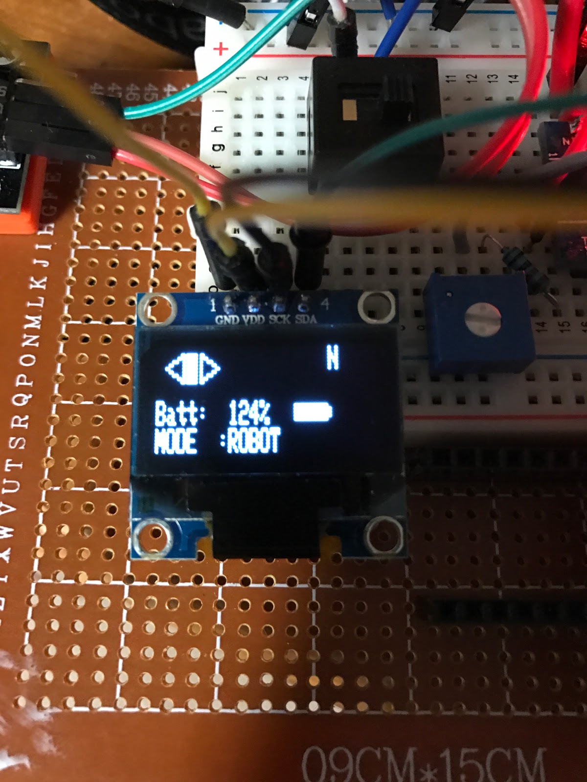
Here's a downer at 4V, my ADC already maps it to 1023 so if you use the above values. Your battery will always be at 100%.
Bad ADC.
Well the solution is simple you just gotta test out your nano to see at what voltage it will give you the maximum digitized level of 1023. For me its at about 4V. Yours might be different. When you do figure it out, then you'd repeat the same steps as above to figure out your R2. Then adjust your R2 using a pot, and then use those values to calculate the lower limit voltages.

So the next step is to Map your Voltages into actual percentage. Lets say your min and Max are 3V to 4V. You'll need to convert these back to the corresponding digital levels multiplying the ratio (1023/4). This is the slope of your ADC mapping (run by 4-0V and rise by 1023-0). Once you have your digitized voltages you'll need to map them into percentage. For 3V - 4V the levels are 767 and 1023. If you graph this digitized levels as x axis and 0 to 100% as y axis. You can calculate the slope and your y intercept. And then in the code it is going to look something like this:

float  x = analogRead(A7); //(Read across your R2)
float percentage = x*slope - yIntercept;
Then you can display your percentage on the OLED by casting it into an integer
display.display((int) percentage);


Tuesday, February 21, 2017

Receiver Board Instruction

Similar to the Controller Board, the Receiver board also consists of an Arduino Nano and a NRF24L01 transceiver and the connection is exactly like the controller board.
Below are the list of components that go into the Receiver Board:
1 Arduino nano
1 NRF24L01
1 L298N Motor Driver
1 Servo
1 Brushed DC motor
1 Logic Level Mosfet
3 1W LEDS
1 Switch
1 5V Regulator

Here are the steps to wire up the Receiver board

Step 1: High Torque Servo
Every servo has 3 pins. 2 of them are for the power and they are usually color coded

  • Attach yellow wire to Nano Pin D2
  • Attach orange wire to the 5V pin on the L298N Motor Driver (this is ideal because you do not want the share the 5V rail with the Arduino board since it is already supplying the transceiver, the Servo does draw a lot of power and lucky for us, motor driver happens to have a nice on board 5V regulator).
  • Attach the GND to ground.
Step 2: Brushed DC Motor
  • Attach + to + output of the L298N 
  • Attach - to - output of the L298N
Step 3: LED 
Same as DC motor, but on the other outputs. The code will take care of the controls

Step 4: L298N Motor Driver
  • Attach 12V pin to your battery
  • Attach GND to ground
  • attach EN1 to pin D5 on the Nano
  • attach IN1 to pin D3
  • attach IN1 to pin D4
  • attach IN2 to pin D6
  • attach IN2 to pin D9
Step 5: Switch
First component the battery sees is this master switch.

Monday, February 20, 2017

Control Board Instruction

Below is my instruction on building the control board:

Step 1: Part of List

You will probably first want to prototype it. Here is the parts that you'll need for the control board.

  • 1 Arduino Nano
  • 2 Joy Stick/Thumb Stick modules/Break-out boards,
  • 1 OLED I2C display
  • 1 NRF24L01
  • 1 Battery packs 6V - 9V
  • 1 Micro USB for the Nano


Step 2: NRF24L01

Lets begin assembling the NRF24L01 Module. Start with connecting the Vcc to the 3.3V supply. Do be extra careful on this step. You do not want to sort this pin to 5V or higher it will FRY your module. My best advice is to get the adapter board that this modules sits right on which regulates power up to 15V. This also takes care of the power problem with this module. Since the 3.3V rail on the Arduino does not supply enough power for optimum range. There are many libraries out there but the one that was used in my code is probably the best library. It offers optimum range and signal strength. Contact me if you have trouble installing this library.

  • Next connect the Ground Pin to the Ground.
  • Connect CE pin to pin 7 on the Nano
  • Connect CS pin to pin 8 on the Nano
  • Connect CLK pin to pin 13 on the Nano
  • Connect MOSI pin to pin 11 on the Nano
  • Connect MISO pin to pin 12 on the Nano
  • The last pin is not needed at the Moment.
After wiring the pin you are ready to test out.
On the Arduino IDE go to example and load an NRF24L01 example to the Nano Board 1, then do the same thing to the Nano Board 2. Make sure that one is a client and the other is a server. And then use Serial Monitor to validate the communication. You should be getting messages from one device to another. 

Step 3: Joy Stick Modules

These are fairly straight forward. Each Joystick should have 5 pins, VCC, GND, X, Y, and SW. 
  • Connect VCC to 5V on the Nano
  • Connect GND to ground
  • Connect X axis to A3
  • Connect Y axis to A2
  • Connect SW to D2
Similarly on the other joystick connect X2 to A1, Y2 to A0 and SW to D3
Now upload my code to the Nano board and use Serial Monitor to test the Joy Sticks modules to see if you are reading correct output when you flip the Joy Sticks. You should be getting raw values from 0 to 1023 due to the output of the 10 bit built in ADC (analog to digital converters) which converts 5V Analog voltages to digital levels.

Step 4: OLED 

You'll need a driver for this OLED which I suggest the SSD1306 from Adafruit. Just search for this library and install it in the arduino software (message me if you don't know what this means). Here is how you wire up the OLED display:
  • Connect 5V to either 5V rail or 3.3V supply rail on the Nano
  • Connect SDA and SCL pin to A4 and A5 (I2C pins)
  • Connect GND to Ground
Run my code and you should see the OLED turns on. If it doesn't then you'll probably have a different address. The way I2C communication protocol works is that one of its first data package that the master (in this case your Arduino Nano) sends out contains the addressing byte to identify that slave. In this case would be your OLED. You might want to run a address scanner to identify what your address is for your OLED. 

Step 5: Battery

Probably the easiest step. If you had a 9V smoke alarm battery you can connect the 9V supply to the Vin of your nano. GND to the GND of your nano and it would light up. Other wise you can by 4 1.5 AAA batteries and connect them in series which produce 6V total. That should also be enough for your Nano Board. 

And there you have it. Your very own controller board. 


Saturday, February 4, 2017

Welcome!

Greetings,

If you are looking for an engineering project for your capstone, your hobby, or your personal enjoyment to gain experience or to put on your resume or to impress your mentors. This is it.

This project hits ALL 3 of the engineering fields, mechanical, electrical and computer science. I will show you how to make your own.


.